|
| Paver Lights |
|
INSTALLATION INSTRUCTIONS FOR PAVER LIGHTS BY KERR LIGHTING
Thank you for purchasing your "Paver Light" kit by Kerr Lighting,
Please read the entire instructions before commencing and follow all
the instructions carefully.
PARTS LIST
|
|
| 8 pack Paver Lights with transformer |
|
14 pack Paver Lights with transformer |
- (for 8 pack Paver Lights with transformer n )
- (for 14 pack Paver Lights with transformer n )
- 8 Paver Lights base fixtures
- 8 Paver Lights lenses
- 8 Receptacles (sockets)
- 8 4 watt lamps
- 16 blue quick connectors
- 1 low voltage outdoor transformer
- 50 ft. low voltage cable
- Installation Video
|
|
- 14 Paver Lights base fixtures
- 14 Paver Lights lenses
- 14 Receptacles (sockets)
- 14 4 watt lamps
- 28 blue quick connectors
- 1 low voltage outdoor transformer
- 100 ft. low voltage cable
- Installation Video
|
|
|
TOOLS YOU WILL NEED
- Pair of pliers.
- Knife or other tool sharp enough to cut through low voltage cable
- Star head screw driver.
- Remove all items from the carton and check against the parts list above. There are two parts lists - be sure you are checking off against the coordinating kit purchased.
- Pre-assemble all of your fixture by first inserting your lamp into
your socket. Secure the lamp into the socket holder and feed both
lead wires out of the end of the base of the fixture. Lead wires are
now outside of the Paver Lights.
- Draft a layout of your project to be lit and the location of your outdoor power source. Determine where you wish your Paver Light fixtures to be placed. For good lighting distribution a 3 to 5 foot space between fixtures is recommended. (Note: transformers placed near swimming pools or other water sources should be plugged into a GFCI protected outlet and the control unit should be mounted at least 10 feet from the edge of the water). Paver Lights should not be installed in low lying areas where water tends to puddle.
- Connect your transformer to the low voltage cable.
- Run your low voltage cable from the transformer around the perimeter of your project. Remember to leave some slack at each
light to allow for easy connection.
- There are two blue quick connectors for each paver light fixture. Each connector will contain a lead wire from the socket, and will connect each side to your main low voltage wire. The cable at the light fixture will be separated 3 - 4 inches by slicing
down the centre of the cable (be careful not to expose the wire). Open the connector in half and saddle over one half of the cable where you have sliced. One lead wire from the socket fits into the small hole in the connector (it does not matter which of the two lead wires you use).
- Push the lead wire from the socket gently until you see it pass the crimping plate. Push down the crimping plate with pliers to
make the proper connection.
- Fold over the plastic tab until it snaps in place.
- Test your system to ensure all of your fixtures are in place and
are working.
- Once the Paver Lights are properly installed the low voltage cable can now be concealed. The low voltage cable may be placed
directly under your project or along the side of your project in the grass.
- Sit back and enjoy your new outdoor lighting project.
|
IF YOU ARE EXPERIENCING ANY DIFFICULTY, TECHNICAL
ADVICE AND SUPPORT IS AVAILABLE
MONDAY TO FRIDAY 9 a.m. to 5 p.m. EST.
(613) 283-9571
PO Box 446 10 Soper Drive
Smiths Falls, Ontario
Canada K7A 4T4
|
|
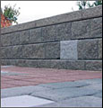
| Retaining Wall Light |
|
INSTALLATION INSTRUCTIONS
Necessary Tools: Pair of pliers; Utility knife; Phillips screw driver
|
|
- Determine where the 6 x 8 Retaining Wall Light fixture will be placed in your landscape retaining wall and the location of your exterior power source. For good lighting distribution, a space if 3 to 5 (.9m to 1.5m) between your fixtures is recommended. The transformer should be located near the exterior pwer source, mounted on a vertical surface 18 (450 mm) above the grade surface. Transformers placed near swimming pools or other water sources should be mounted at least 10 (3m) from the edge of the water.
Note: Transformers should only be used with G.F.I (Ground Fault Interrupted) exterior power sources. Verify that the power source is G.F.I. and if not
STOP
Have a G.F.I. power source installed to appropriate electrical codes. Connection of transformer (plug-in) to G.F.I. power source should be the last step in the installation process. Do not have power on while working on the light fixture installation.
- Construct the landscape retaining wall in accordance with the manufacturers instructions until reaching the level where the light fixtures are to be installed. Backfill and compact the soil behind the wall according to the instructions up to the level of the light fixtures. Place the light fixture in the desired location then line up the light fixture with the concrete retaining wall units such that the side edges just touch. Now proceed to wire the lights as indicted in Step 3.
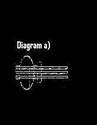
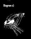
- Run the appropriate length of low voltage wire from the transformer area to the location directly behind the light fixtures in the wall. Remember to leave some slack in the wire at the transformer and the light fixtures to allow for easy connection. Provide a shallow trench to bury any low voltage wire that is exposed. To connect the light fixtures to the low voltage wire, follow the instructions and diagrams a) through c).
- Install the remaining courses of the retaining wall units and backfill as recommended by instructions. The 6 x 8 Retaining Wall Light fixture is capable of supporting the weight of the concrete units placed in top of them.
Note: To support weight evenly, center two wall units over the 6 x 8 Retaining Wall Light fixture in the retaining wall. With the light fixture in place, the lens can be unfastened for removal and replacement of the fixture bulb.
- Install the transformer to a vertical wall surface using the screws provided. Install screws at 3 ? (83mm) spacing from each other located approximately 18 (450mm) above the grade surface. Mount the photoelectric sensor, using the screws provided, to a vertical surface near the transformer. Connect the low voltage wire ends to the screw terminal points on transformer, making sure enough insulation has been stripped away to allow for a positive connection.
- Plug transformer into the G.F.I. exterior power receptacle to complete the job.
|
|
WARNING
TURN POWER OFF BEFORE INSTALLING OR REMOVING
CONNECTOR. ALLL ELECTRICAL WORK SHOULD BE DONE
ACCORDING TO APPROPRIATE ELECTRICAL CODES. USE ONLY
INSULATED WIRE. DO NOT STRIP INSULATION
|
|
   |
|
- Insert 2 or 3 un-stripped wires completely into the connector and check the wire is positioned by looking through the translucent connector body.
- Hold tool perpendicular to the wires and make the connection by driving the cap down flush with the edge of the connector body.
PRECAUTIONS
Avoid eye contact. Wear appropriate eye protection such as safety glasses or chemical goggles. Avoid
prolonged skin contact. Wear impervious gloves. Keep containers closed
SUGGESTED FIRST AID
Eye contact: Flush eyes with plenty of water for at least 10 minutes. Call a physician.
Skin contact: Wash with soap and water.
|
|